A fireproofing quality control example is most useful when it reflects what happens on an active commercial jobsite: steel is being released floor by floor, MEP trades are creating new penetrations daily, inspections are approaching, and the schedule leaves little room for correction. Quality control cannot be a closeout exercise. It has to begin before material arrives and continue until every rated assembly is documented and ready for inspection.
For general contractors and construction managers, the standard is straightforward: the installed system must match the tested and listed system, meet the project specifications, and perform as intended in a fire. Getting there requires disciplined coordination, qualified installation, measurement, verification, and records that answer an inspector’s questions without creating a scramble.
What Quality Control Must Protect
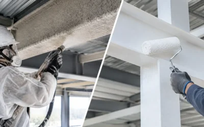
Passive fire protection is not a finish trade. Spray-applied fire-resistive material (SFRM), firestop systems, and rated joint systems protect the continuity of a building’s fire-resistance strategy. A gap around a pipe, an unprotected beam connection, or insufficient SFRM thickness can compromise an assembly that otherwise appears complete.
That is why quality control is measured against more than appearance. The installation must align with the applicable UL-listed assembly, manufacturer installation instructions, approved submittals, project drawings, NFCA requirements where applicable, and the authority having jurisdiction’s expectations. When those documents conflict or a field condition does not fit the selected system, the correct response is not to improvise. It is to stop, evaluate the condition, and obtain an approved path forward.
The trade-off is real. Early verification takes time from a fast-moving sequence. Rework after a failed inspection takes much more time, often affects several trades, and can hold up ceilings, finishes, occupancy, or turnover.
Fireproofing Quality Control Example: A Commercial Floor Buildout
Consider a six-story office and medical buildout with structural steel requiring SFRM and multiple rated wall assemblies receiving firestop. The general contractor releases the third floor for fireproofing while framing, plumbing, electrical, and HVAC work continue in adjacent areas.
Before installation begins, the fireproofing subcontractor reviews the contract documents and approved submittals with the superintendent. The review identifies the required hourly ratings for beams, columns, floor assemblies, and rated partitions. It also confirms the specified Isolatek SFRM product, the listed UL designs, required thicknesses, substrate preparation requirements, and areas that need masking or protection from overspray.
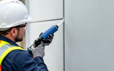
For firestopping, the team reviews the penetration schedule and the relevant wall and floor assembly types. A copper pipe through a gypsum wall, a bundled data cable tray through a shaft wall, and a duct penetration through a concrete floor may each require different listed systems. The correct selection depends on annular space, penetrant type and size, sleeve conditions, backing material, movement requirements, and the rating of the assembly. A product name alone is not a firestop system.
Step 1: Verify the Conditions Before Work Starts
The field lead walks the work area before mobilization. Steel is checked for conditions that could affect SFRM bond, including excessive oil, loose scale, moisture, or incompatible coatings. The team confirms that metal deck, attachments, and interfaces match the UL design being installed.
For firestopping, the lead identifies conditions likely to create problems later. These include oversized openings, missing sleeves, mixed penetrants, incomplete wallboard, unsealed top-of-wall joints, and penetrations installed too close together for the selected system. Findings are communicated promptly to the GC and responsible trade. This protects the schedule because issues are addressed before crews install a system that will have to be removed.
Step 2: Establish a Measurable SFRM Standard
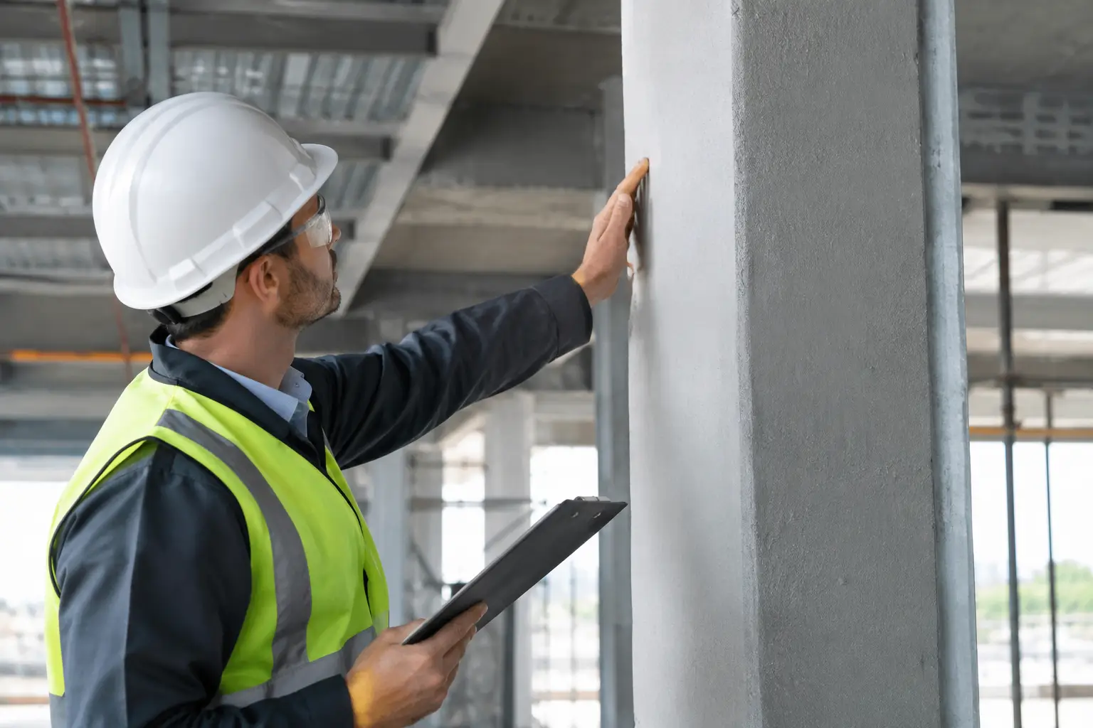
The approved UL design calls for a specified average thickness and a minimum thickness at individual test points. The crew does not rely on visual judgment. During application, the foreman checks thickness with calibrated gauges at representative locations and verifies that the material fully covers the steel profile, including flanges, webs, corners, and areas behind obstructions where required.
The inspection record identifies the floor, grid location, member type, required thickness, measured thickness, date, and responsible installer or supervisor. If a reading is below the required minimum, the condition is corrected immediately and remeasured. Areas damaged by follow-on trades are tracked for repair rather than left for an uncertain final walk.
Density testing may also be required by the project specifications, manufacturer, or testing agency. Where it applies, sample collection and testing must follow the specified procedure. Thickness and density are related but not interchangeable. A thick application that lacks the required density, or a dense application installed too thin, may not satisfy the tested design.
Step 3: Match Every Firestop Installation to a Listed System
As MEP rough-in progresses, the firestop crew verifies each condition before installation. For example, a two-inch steel pipe penetrating a two-hour concrete floor may be assigned a specific UL system using a defined sealant depth, backing material, annular-space range, and packing configuration. The installer confirms that the actual field condition falls within those listed limitations.
If the opening is larger than the listed range, the team does not fill the excess space with more sealant and call it compliant. It may require an engineered judgment, a different listed system, a sleeve correction, or coordination with the design team. The answer depends on the condition and the governing project requirements.
Each completed firestop location is labeled or otherwise identified according to the project’s documentation plan. The record captures the location, assembly rating, penetrant type, selected UL system, product used, installer, installation date, and photographs before concealed work closes the area. Clear photos should show the opening, penetrant, completed system, and identifying information where practical.
Step 4: Perform Independent Internal Checks
A foreman should inspect work continuously, but a second set of trained eyes catches issues that production crews can miss. Internal quality checks should be performed before requesting formal inspection and before ceilings or shaft walls make access difficult.
For SFRM, the reviewer checks thickness records, coverage, adhesion concerns, repaired damage, and interface conditions. For firestop, the reviewer confirms that the system matches the actual penetrant and substrate, required backing is present, sealant depth is adequate, and the installation is clean and continuous. The reviewer also checks rated joint systems at head-of-wall and perimeter conditions, where movement capability is often as critical as fire rating.
At Colonial Fireproofing, this inspection-first discipline is supported by field experience with UL-rated systems and certified STI instructor oversight. The goal is not merely to complete an installation. It is to present work that is prepared for review and defensible in the closeout file.
Documentation That Keeps Inspections Moving
Quality control records should be organized as the work proceeds, not assembled from memory at project closeout. A practical package includes approved submittals, UL system references, manufacturer data, material batch information when required, SFRM thickness and density records, firestop location logs, photographs, deficiency reports, repair confirmations, and inspection sign-offs.
This documentation matters when an inspector asks which system was installed at a particular penetration, when a facility owner needs records after turnover, or when a late field change affects a rated assembly. It also gives the GC a clear way to confirm installed scope against the schedule and avoid carrying unresolved life-safety items into punch list.
The level of documentation should match the project. A hospital, laboratory, multifamily high-rise, or occupied renovation may require more detailed tracking than a small tenant improvement. But every project benefits from traceable records and a defined process for corrective work.
Common Failures This Process Prevents
Most fireproofing failures are not caused by a lack of available products. They result from missed coordination, incorrect system selection, poor substrate conditions, insufficient thickness, unprotected changes made by another trade, or documentation that cannot prove what was installed.
One common example is a penetration made after the firestop crew has completed an area. If the opening is not added to the tracking process, it can remain unprotected above a finished ceiling. Another is SFRM damage from hangers, ductwork, or subsequent construction. A reliable quality-control process includes periodic return walks so those conditions are identified before final inspection.
The best time to resolve a fire-resistance issue is when the assembly is open, the responsible trade is still mobilized, and the correction can be scheduled without disrupting finishes. That requires active communication between the superintendent, MEP coordinators, inspection team, and passive fire-protection contractor.
A compliant building is built one verified condition at a time. Bring the fireproofing specialist into the coordination process early, keep the work visible until it is checked, and treat documentation as part of the installed system. That approach protects lives first, while giving the project team the clearest path to a clean inspection and a controlled closeout.