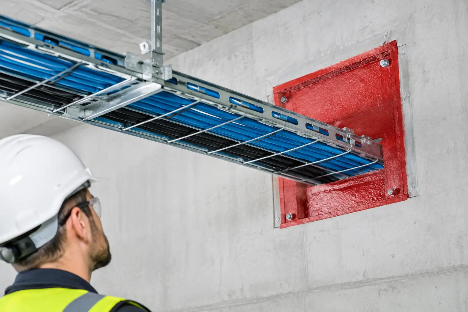
A cable tray can look like a straightforward MEP coordination item until it crosses a rated wall or floor. At that point, firestop cable trays become a life-safety scope with real consequences for the schedule. An unprotected opening can allow fire, smoke, and hot gases to compromise a compartmentalized building long before occupants or responding crews need that barrier to perform.
For general contractors, superintendents, and facility teams, the challenge is not simply getting sealant around a tray. The work must match a tested and listed system, accommodate the actual tray and cable conditions in the field, and remain verifiable at inspection and closeout. That requires early coordination, disciplined installation, and documentation that answers questions before they become a failed inspection or a rework ticket.
Why Firestop Cable Trays Require System-Specific Design
Cable trays are rarely static, empty penetrants. They may carry power, data, controls, security, or life-safety cabling. Their loading can change late in construction, and their configuration may include ladder tray, solid-bottom tray, basket tray, conduit transitions, splices, or multiple cable types. Each of those details can affect which listed firestop system applies.
A rated assembly does not accept a one-size-fits-all solution. The rating of the wall or floor, the opening size, tray material, cable fill, annular space, penetrant arrangement, and required movement all matter. A system tested for a steel ladder tray with a defined cable load through a gypsum wall is not automatically appropriate for a wider tray, a concrete floor, or a tray that was filled after the original installation.
This is where jobs can go wrong under pressure. A field crew may see an open perimeter and install a familiar product, but the product alone does not establish compliance. The complete configuration must align with a UL-listed assembly and the manufacturer’s installation requirements. Material substitutions, oversized openings, missing backing, insufficient depth, or cable fill beyond the tested condition can leave a penetration unsupported by the listing.
The right question is not, “What can we put around this tray?” It is, “Which tested system matches the installed condition, and what must be coordinated so it can be installed exactly as listed?” That distinction protects the rated assembly and reduces uncertainty for the authority having jurisdiction.
Coordinate the Opening Before the Tray Arrives
The cleanest cable-tray firestop installation begins before the penetration is cut or the tray is set. Firestop contractors, electrical contractors, framing teams, and concrete trades all influence the final condition. When that coordination happens late, the firestop scope inherits irregular openings, inaccessible surfaces, unsupported cables, and details that may not match an available listed system.
During preconstruction or early field review, confirm the rated barrier location, hourly rating, tray type and dimensions, anticipated cable loading, and whether future cable additions are expected. Verify the opening layout and clearances required by the proposed system. It is also worth identifying who owns sleeves, framing, edge protection, tray supports, and cable supports. These are small scope boundaries on paper, but they determine whether the firestop crew can complete compliant work when the area is ready.
Future capacity deserves particular attention. A tray installed at partial fill may need additional circuits after turnover. If the selected system cannot accommodate that anticipated fill or cannot be modified without major disturbance, the owner may inherit an avoidable maintenance issue. In some conditions, a re-enterable or easily serviceable firestop approach may be appropriate. In others, the rating, smoke requirements, or assembly geometry may require a more permanent configuration. It depends on the listing and the building’s operational needs.
For occupied facilities, coordination also includes access. A penetration above a hard ceiling, behind equipment, or near active operations may be technically firestoppable but difficult to inspect or maintain. Planning the work with future access in mind is a practical way to avoid corrective work after occupancy.
Common Conditions That Create Rework
The most frequent issues are not complicated. They are conditions left unresolved until inspection is near: cable trays installed too close to adjacent penetrations, oversized openings without an applicable system, cables unsupported at the penetration, tray supports that interfere with the required firestop geometry, and cable additions that exceed the listed configuration.
Another common problem is treating the wall face as the entire scope. Many systems require specific treatment on one or both sides of the assembly, defined packing material, prescribed sealant depth, or components that must be installed in a particular sequence. If one side becomes inaccessible after other trades close in the space, the correct installation may no longer be possible without opening finished work.
A field-ready firestop review catches these conditions early enough to preserve options. That is usually faster than requesting a last-minute engineering judgment, changing the tray route, or removing installed cable to reconstruct the penetration.
Installation Is More Than Applying a Firestop Product
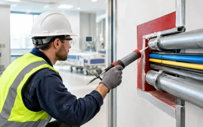
A compliant cable tray penetration is built to the listed detail, not to appearance alone. The crew must prepare the opening, confirm the substrate and dimensions, install the specified backing or packing material, maintain required depths, and apply the approved firestop components at the prescribed locations. Where a system includes wraps, blocks, pillows, collars, or other devices, those components must be installed with the correct orientation and attachment method.
Cable management matters as well. Cables must be arranged and supported so the system can perform as tested. Loose bundles, voids created by uneven cable placement, or unsupported cable weight can affect both installation quality and future serviceability. The tray itself must not create a bypass around the firestop system.
Quality control should occur while the work is visible. Once ceilings are closed or dense MEP work advances, correcting a missing component becomes more expensive and disruptive. Inspection-focused crews verify the listing, opening dimensions, materials, depth, substrate condition, and identifying labels or markings before moving to the next area.
Colonial Fireproofing approaches these details as a trade partner accountable for the completed rated assembly, not as a last-stop sealant installer. Certified oversight, manufacturer-specific systems, and access to thousands of UL-rated firestop assemblies help teams resolve field conditions without improvising a life-safety detail.
Documentation Keeps the Work Defensible
The installed work and the closeout package should tell the same story. For cable tray penetrations, useful documentation typically identifies the location, rated assembly, applicable UL system, firestop manufacturer, installed materials, installer information, and photographs of completed work. On larger projects, tracking by floor, room, grid line, penetration number, or drawing reference makes turnover and future maintenance far more manageable.
Documentation is not paperwork added after the fact. It supports inspection, confirms scope completion, and gives the owner a record of what is behind finished surfaces. If a cable contractor needs to add conductors later, the facility team can review the original system rather than guess at what was installed.
It also protects schedule control. When the firestop subcontractor can provide submittal information promptly and document completed penetrations in an organized format, the project team has fewer open questions at final inspection. That matters when a temporary certificate, tenant turnover, or phased occupancy depends on closing life-safety items quickly.
A Better Field Process for Active Projects
The best results come from treating firestop cable trays as a coordinated sequence rather than a punch-list category. Review anticipated conditions early, select applicable systems before installation where possible, inspect openings before they disappear behind cable and finishes, and document work as it is completed.
There will always be exceptions. Existing conditions may not match drawings. A late-added tray may cross a rated barrier in a congested shaft. A system shown in the submittal may not fit the field geometry. Those are the moments when a qualified firestop specialist should assess the actual condition, identify a compliant path forward, and communicate the impact immediately. Speed matters, but no schedule recovery plan should depend on an untested shortcut.
When cable trays cross rated barriers, the goal is simple: preserve the barrier’s performance, give inspectors a clear basis for approval, and leave the owner with a system that can be understood and maintained. Address the penetration before it becomes hidden work, and it is far more likely to stay off the punch list.