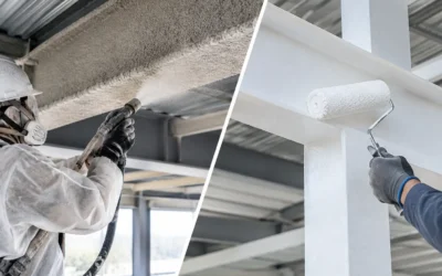

A beam can look fully covered and still fail its fire-resistance requirement. That is the risk with SFRM thickness: visual coverage is not proof that the installed material matches the tested and listed fire-resistive assembly. On an active commercial project, the required thickness must be established before spraying begins, controlled while the work is underway, and verified before the assembly is presented for inspection.
For general contractors and construction managers, getting this right protects more than an inspection date. It protects the structural fire rating, avoids removal and reapplication after other trades have mobilized, and keeps life-safety scope from becoming a late-stage schedule problem.
What Determines SFRM Thickness?
Spray-applied fire-resistive material is not specified by a universal thickness chart. The required depth is driven by the listed assembly and the conditions of the steel or deck being protected. The governing source is typically the applicable UL design, supported by the project specifications, code requirements, approved submittals, manufacturer instructions, and direction from the authority having jurisdiction.
A two-hour or three-hour rating alone does not tell the installer how thick the material must be. The required SFRM depth can change based on the member type, its shape, the type of fire-resistive material, and the design parameters used in the listing. Columns, beams, joists, girders, and floor or roof deck assemblies may each have different requirements within the same building.
For structural steel, one of the key variables is the W/D ratio. This compares the weight of a steel member to the heated perimeter exposed to fire. A heavier member with less exposed perimeter generally heats more slowly than a lighter member with more exposed perimeter. That difference affects the protection required to achieve the rated performance established by the tested design.
The contour of the application also matters. SFRM may be applied around the member profile or in a boxed configuration, depending on the listed assembly. Changing the application method in the field can change the heated perimeter and invalidate the thickness assumption. A crew cannot simply box out a member because it appears easier to spray, nor can it follow the profile when the approved design requires boxed protection.
The UL Design Is the Installation Road Map
A product data sheet can describe material properties, application ranges, and general performance. It does not replace the UL-listed assembly selected for the project. The UL design identifies the conditions under which a fire-resistance rating was established, including the assembly construction, steel member characteristics, required fireproofing thickness, and application configuration.
This distinction becomes especially important when field conditions do not match the plans cleanly. A steel size substitution, a revised framing detail, additional bracing, a different deck profile, or an unanticipated concealed condition can affect the applicable design. Treating these changes as minor can create major inspection exposure.
The right response is to review the condition before it is covered. The project team may need confirmation from the design professional, a revised approved submittal, a manufacturer-supported engineering judgment where appropriate, or a different listed assembly. The solution depends on the condition. What does not work is applying material to a guessed thickness and hoping the issue remains unnoticed.
Colonial Fireproofing approaches SFRM scope as a coordinated fire-rated system, not a commodity spray operation. That means confirming the approved design, identifying field conditions that could affect compliance, and communicating early enough for the project team to make a defensible decision.
Why Nominal Thickness Is Not Enough
SFRM is commonly described in terms of a nominal thickness, but installation acceptance is based on the requirements of the specific design and project documents. Field-applied material has variation. Steel flanges, webs, corners, deck flutes, transitions, and congested framing create areas where thickness can build up or fall short.
A field crew must account for that variation during application. If the required thickness is treated as a target average without regard for minimum readings, thin areas can be missed until special inspection or final review. At that point, correcting the work may require containment, respraying, cleanup, retesting, and coordination with trades that have already installed ceilings, ductwork, conduit, or finishes nearby.
Thickness also cannot be evaluated separately from density. Many SFRM systems are formulated and tested at a specific installed density range. Applying material too light, too heavy, too wet, or without proper mixing can affect performance and compliance. The material must be installed according to the manufacturer’s instructions and the approved system, using controlled equipment settings and qualified field practices.
Surface conditions matter as well. Loose mill scale, oil, excessive rust, moisture, incompatible coatings, and improperly prepared substrates can compromise adhesion. A correct thickness does not cure a bond problem. Before spraying begins, the steel and deck need to be reviewed for conditions that could prevent the material from performing as intended.
Verifying SFRM Thickness Before Inspection
Thickness control should begin with a pre-installation review, not with a correction list. The fireproofing contractor, general contractor, special inspector, and other affected trades should understand which assemblies will receive SFRM, the applicable UL designs, expected thicknesses, and the project’s testing and documentation requirements.
During installation, experienced crews check coverage and depth continuously rather than waiting for a final pass. This is particularly valuable at member transitions, beam-to-column connections, deck interfaces, edge conditions, and areas crowded by mechanical or electrical work. Those locations are often where access is limited and repairs are most disruptive.
Formal thickness and density verification is commonly performed in accordance with the project requirements and applicable ASTM testing standards, including ASTM E605 where specified. Testing frequency, sampling locations, acceptance criteria, repair procedures, and reporting requirements should be established before work proceeds. The special inspector’s role is independent verification, but the installing contractor remains responsible for delivering compliant work.
When a test reveals a deficiency, the best outcome comes from fast, documented correction. The affected area should be identified, repaired with compatible material and methods, allowed to meet required conditions, and retested when required. A vague statement that an area was “touched up” is not closeout documentation. Inspection-ready records should demonstrate what was tested, where it was tested, what was found, and how nonconforming work was resolved.
Coordination Prevents Thickness Problems
SFRM thickness issues often begin as coordination issues. Steel must be accessible for proper application. Hangers, clips, duct mains, cable trays, and piping installed too early can block coverage or create difficult-to-inspect voids. Other trades also need to understand that later penetrations, attachments, or damage to a fireproofed assembly may require repair.
The practical sequence varies by project, but the principle does not: identify access constraints before they become concealed-condition problems. A fireproofing contractor should walk critical areas with the superintendent, flag challenging elevations or dense mechanical zones, and establish a workable sequence around the schedule.
Temperature and environmental conditions deserve the same attention. SFRM systems have manufacturer limits for substrate temperature, ambient conditions, curing, and protection from weather or physical damage. On projects with open structures, winter conditions, temporary heat, or phased enclosure, those requirements can affect when the material can be applied and when it can be tested. Pressing ahead outside approved conditions may save a day on the schedule and cost weeks in corrective work.
Common Field Assumptions That Create Rework
The most expensive errors are often based on assumptions that sound reasonable on a busy site. “It looks thick enough” is not an acceptance standard. “We used the same thickness on the last job” ignores differences in member size, rating, contour, and design listing. “The inspector will tell us if there is an issue” shifts a controllable quality check to the latest and most disruptive point in the process.
Another common mistake is treating a repair as simple cosmetic work. If SFRM is damaged by later construction, the repair needs to restore the required system condition, including thickness, continuity, adhesion, and finish appropriate to the listed assembly and project requirements. The repair area may also need documentation or retesting depending on its extent and the inspection plan.
The disciplined approach is straightforward: confirm the correct design, install to the required configuration and depth, verify the work, and preserve records that support closeout. That process is not extra administration. It is what allows a rated assembly to be defended when the project is under inspection pressure.
Before steel becomes inaccessible or the schedule tightens around overhead work, bring the SFRM scope into the coordination conversation. A short technical review early in the sequence can prevent a thin application, a failed test, and a costly return to work that should have been completed right the first time.