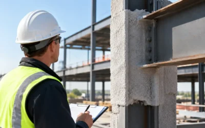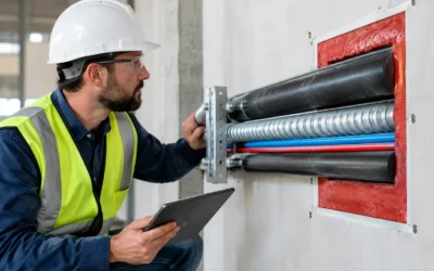
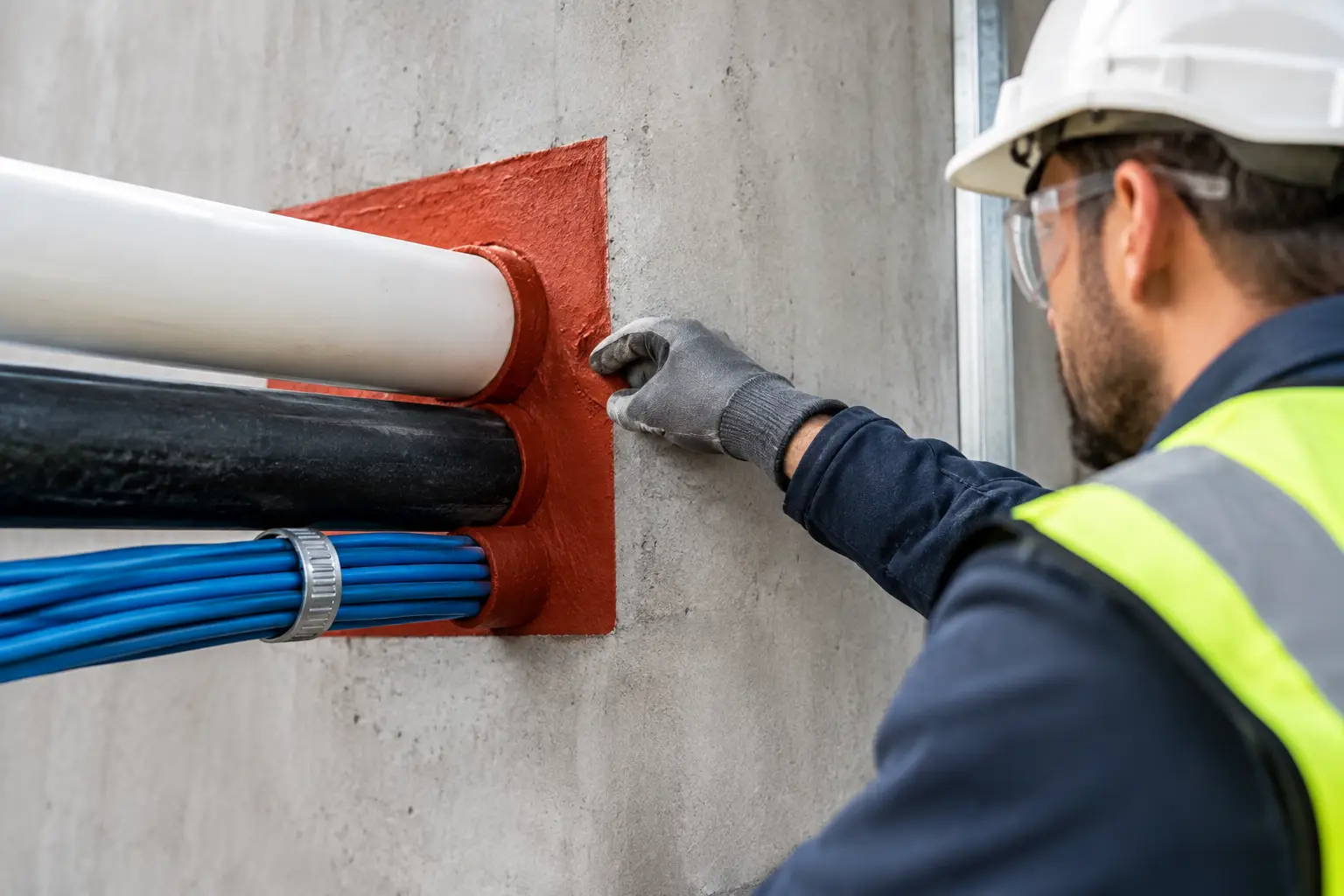
A firestop detail can look straightforward on a plan, then become a failed inspection once the actual conditions are exposed above the ceiling. A proper penetration firestop selection guide starts with the field condition, not a tube of sealant. The penetrant, the rated assembly, the opening geometry, movement expectations, and the approved tested system must all work together.
For general contractors and construction managers, the goal is not simply to fill an opening. It is to restore the fire-resistance rating of the wall or floor after mechanical, electrical, plumbing, and low-voltage trades have passed through it. The selected system must be installed exactly as tested, documented clearly, and ready for the authority having jurisdiction to inspect.
Why penetration firestop selection affects the schedule
Firestopping is frequently treated as a late-stage punch item. That approach creates avoidable risk. By the time crews are closing walls, installing ceilings, or preparing for final inspection, access may be limited and penetrations may no longer match the assumptions made during estimating.
An unapproved field condition can require engineering review, added backing material, penetrant correction, or opening modifications. Those are not minor details when multiple trades are waiting on ceiling closure or occupancy milestones. Selecting the right listed system early protects the rated assembly and keeps corrective work from becoming critical-path work.
The standard is simple: a listed firestop system must match the condition in the field. A system number alone is not a substitute for verification. If the tested assembly calls for a specific wall type, annular space, mineral wool depth, sealant thickness, or cable arrangement, those requirements govern the installation.
Start with the rated assembly, not the penetrant
The first question is where the penetration occurs. Is it a gypsum wall assembly, concrete masonry wall, cast-in-place concrete floor, metal deck floor, shaft wall, or another rated construction? The answer establishes the boundary being protected and narrows the possible UL-listed systems.
A one-hour wall and a two-hour floor are not interchangeable conditions. Even assemblies that appear similar may have different stud configurations, board layers, thicknesses, or rated designs. The firestop system must be compatible with the specific construction, including the fire-resistance rating required by the drawings and code.
Field teams should verify the following before selecting a system:
- The substrate and assembly type, including wall or floor thickness
- The required hourly rating and whether an F, T, or L rating is specified
- Whether the opening was cast, core drilled, sleeved, or field-cut
- The opening size, shape, and actual annular space around each penetrant
- Whether the installation is accessible from one side or both sides
That information should be confirmed against approved drawings and existing conditions. Firestop selection based on a generic “rated wall” description is where many compliance problems begin.
Understand F, T, and L ratings
The F rating measures the time a firestop system resists passage of flame through the opening. The T rating addresses temperature rise on the unexposed side, which is particularly significant where combustible materials or people may be nearby. The L rating measures air leakage through the system at ambient and elevated temperatures.
Not every penetration requires the same combination of ratings. The project specifications, code requirements, tested assembly, and AHJ expectations determine what applies. A system with the correct F rating may still be unsuitable if the specification requires a T rating or a defined L rating. This is why selection cannot be reduced to “find a one-hour system for a one-hour wall.”
Identify the penetrant and its behavior in a fire
The material passing through the opening changes the system selection. Metallic pipe, insulated pipe, conduit, cable bundles, cable tray, plastic pipe, mixed penetrations, and HVAC components behave differently under fire exposure.
Combustible penetrants such as PVC, CPVC, ABS, and certain insulated piping may melt or burn away. The listed system may require an intumescent sealant, wrap strip, collar, cast-in device, or a combination of components that expands to close the opening left behind. Substituting ordinary sealant for a tested intumescent component is not an acceptable field adjustment.
Metallic pipe introduces different considerations. Copper, steel, and cast iron can conduct heat, and insulation type matters. Pipe insulation may need to be interrupted, continued through the opening, or protected with a particular system design. A firestop detail that works for bare steel pipe may not be listed for an insulated copper line with a larger annular space.
Cable conditions deserve the same level of scrutiny. A few individual cables, a dense communications bundle, and a cable tray are separate tested conditions. Future cable additions also matter. In telecom rooms, data centers, hospitals, and institutional facilities, a system that can be re-entered without destroying the firestop may be the practical choice. That does not mean choosing a convenient system over a listed one. It means selecting a tested system that supports the anticipated service life of the space.
Match the field condition to a UL-listed system
UL-listed firestop assemblies are tested configurations, not general suggestions. The listing identifies the construction, penetrant, opening range, annular space, fill material, sealant depth, and rating achieved under test conditions. Installation must follow that listing and the manufacturer’s instructions.
A capable firestop subcontractor evaluates the actual opening against the system details before installation begins. With access to more than 3,800 UL-rated firestop assemblies, Colonial Fireproofing can identify workable options without forcing a field condition into the wrong detail.
Pay close attention to variations that often appear insignificant but are not:
- A sleeve may be larger than the listed maximum diameter.
- Multiple penetrants may be spaced closer together than the system permits.
- A cable bundle may exceed the allowed fill percentage.
- The specified mineral wool density or compression may not match the material on site.
- A required sealant bead depth may be impossible without adjusting the opening.
When a condition does not match a tested system, do not improvise. The right response may be to revise the opening, separate penetrants, select another listed system, or obtain an engineering judgment when appropriate. An engineering judgment is a project-specific technical document, not a catch-all replacement for finding a listed system. It should be used deliberately, reviewed early, and retained in the closeout record.
Account for movement, access, and future work
Penetrations through floors and walls are not always static. Building movement, vibration, thermal cycling, pipe expansion, and equipment operation can affect the firestop over time. The system must accommodate the conditions it is expected to see. This is especially relevant around larger piping, rooftop mechanical work, seismic areas, and assemblies adjacent to expansion joints.
Access is equally practical. A system installed from only one side must be listed for that installation method. Above-ceiling penetrations can become inaccessible after other work is complete, so coordination with ceiling, mechanical, and electrical teams matters. The best system on paper will not protect the schedule if no installer can reach the required side of the assembly.
For facilities that expect frequent changes, plan re-entry before the first cable is pulled. Firestop systems designed for future cable additions can reduce disruption later, but they still need clear labeling, documented installation, and maintenance discipline. Uncontrolled cable pulls are a common cause of compromised rated barriers in occupied buildings.
Coordinate before walls close
The most efficient time to resolve firestop scope is during coordination, not after inspection. Review rated-wall locations, shaft conditions, sleeve responsibilities, oversized openings, cable tray routes, and phased turnover areas with the trades creating the penetrations.
Superintendents should also establish a clear handoff: who notifies the firestop contractor when penetrations are ready, who protects completed work from damage, and who confirms no additional services will be added before concealment. A completed firestop system can be compromised in minutes by an uncoordinated cable pull or a new conduit installed through a protected opening.
Quality control should include installed-system labels where required, photos of representative and concealed conditions, system numbers, product records, and location-based documentation. This documentation gives the project team a defensible record for inspections, closeout, and future facility maintenance.
Make selection part of the construction plan
Firestop selection is a life-safety decision with direct schedule consequences. The correct approach is disciplined: verify the rated assembly, define the penetrant condition, measure the actual opening, select a matching listed system, and install it exactly as tested.
When conditions change, bring in a qualified firestop specialist before the wall closes or the inspection is called. Early review is usually a short coordination task. Late correction can mean reopening finished work, delaying turnover, and explaining why a rated assembly was left unprotected. A clean, documented installation gives every trade team something valuable: an inspection-ready project that stays protected after occupancy.